Fluvial Hydraulics and Hydrogeology Experimental Facilities
|
Compound channel flume This channel was originally built in the 1960’s with the purpose of performing studies with free surface flows, with or without mobile bed. Presently, this facility is being used for compound channel flows studies. The flume is a 10 m long and 2 m wide recirculating compound channel. It is made of polished concrete with a bottom longitudinal slope of 0.0011m/m. Separated inlets for the main channel and for the floodplains are installed. For each inlet, the flow discharge is controlled with a valve and monitored through an electromagnetic flow meter with the accuracy of ±0.3 l/s. At the downstream end of the flume, independent tailgates for each sub-channel are used to adjust the water levels in the flume. To perform compound channel experiments, several configurations are possible: i) original smooth channel bed; ii) synthetic grass channel bed; iii) vegetation elements with or without foliage in the interface and iv) obstacles placed in the floodplains.
|
Fluvial Hydraulics Tilting Flume (CIV)The CIV facility consists of a 40.0 m long glass-sided rectangular tilting flume, 2.0 m width and 1.0 m deep cross section. The flume bottom slope can vary from 0% to 2.5%. The CIV was designed to study sediment transport phenomena and is capable of recirculating both water and sediments. The experimental setup includes a closed hydraulic circuit where the discharge (water and sediment) can vary from 0.1 to 1.0 m3/s. Presently, this flume is used in a research project with the objective to run an intensive and systematic laboratory campaign to characterize the maximum local scour depth at complex bridge piers. Tests are being carried out with durations of, at least, two weeks. In the channel, a concrete false bottom was installed in order to obtain two sand filled recess boxes, 5.0 m long and 0.4 m deep. Each of the sand boxes is preceded by a 2.0 m long accelerating ramp and a 7.0 m long fixed-bed reach and is followed by a 3.0 m long fixed-bed reach. This channel configuration allows two tests being carried out simultaneously. The study includes the characterization of the flow around bridge piers, through ADV velocity measurements. |
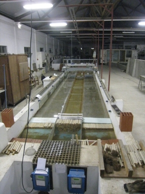
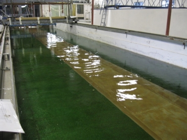
Levee Breach and Dam Failure Experimental FacilityThe objective of this facility is to study earthfill enbankments failures and to gather detailed experimental information on the geotechnical and hydrodynamic phenomena involved in earthfill enbankment breaching and on the hydrodynamics of the flow over the body of dams and leves. The facility allows earth dam tests with a maximum height of 1.25m.The main features of the facility are: i) a storing tank with approximately 90m3 of volume; ii) a pumping circuit with a flow controller with 200 l/s of capacity; iii) a pool representative of a reservoir with a volume of 45m3/s; iv) an implantation space for the earth dam models; v) a 14.75m length flume downstream the earth dams foot. The breach discharge hydrograph is computed as the product of the flow area and the instantaneous velocity, which is an advancement relatively to the studies carried out so far. The experiments contemplate both time and spatial evolution of the breaching process that is accomplished by advanced measuring techniques and instrumentation. 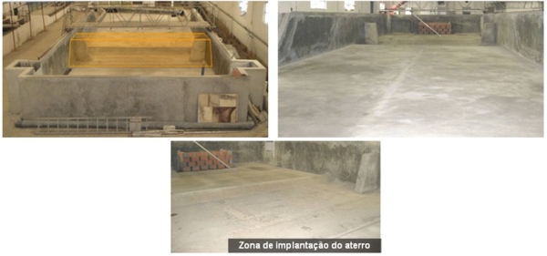 Views of the Levee Breach and Dam Failure Experimental Facility 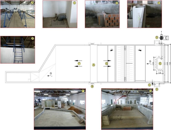 Design Plans of the Levee Breach and Dam Failure Experimental Facility |
This facility was especially built to perform turbidity currents tests. The facility has an upstream tank, the flume, the return hydraulic circuit and the water and sediment mixing tank. The channel is 0.30 m wide, 20 m long and 0.75 m deep. The channel bottom profile was designed with a special configuration to make possible to simulate plunging turbidity currents in reservoirs. An upstream 4.74 m long reach with a bottom slope of 0.014 simulates the river flow approaching a reservoir. An abrupt change in the bottom profile produced by a ramp with a slope of 30º represents the steepness of the front delta deposits in the upper part of the reservoir. Downstream, an 8 m long reach with a slope of 0.014 and a final horizontal 3.75 m long bed reproduce the reservoir in which currents develops. |
|
Fishway Tilting Flume The objective of this large scale pool-type fishway flume, with the ability to perform tests with real specimen, is to study fish behavior in the transposition of river hydraulic structures, like weirs and small dams. The facility is 10 m long, 1.0 m wide and 1.2 m high and as an adjustable slope, with glass-viewing panels on both sidewalls allowing the specimen direct observation while simultaneously monitoring fish movements through the simulated obstacles. It features a fish acclimation chamber (4.0 x 3.0 x 4.0 m), at the downstream end of the channel, and two slot gates, positioned at its upstream and downstream ends, to control the discharge and water level within the structure. The main channel can be adjustable, being the hydraulic structures, designed to mimic previously recorded obstacles, placed in it. Presently, the flume is used to carrying out tests to study the effects of instream structures on the migratory movements of Iberian fish species and define mitigation measures for improving connectivity in Portuguese rivers. 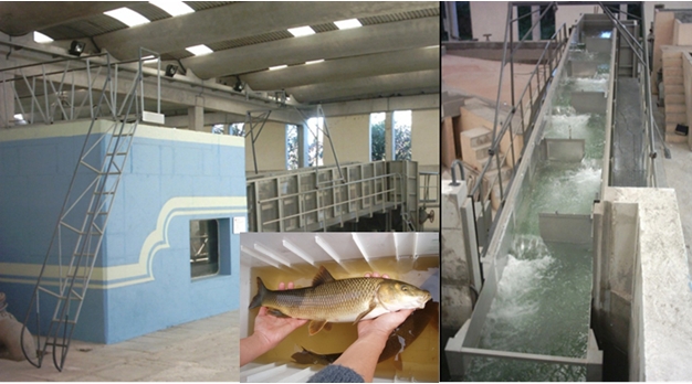 General views of the fishway tilting flume |
|
Artificial Aquifer Facility The artificial aquifer facility (or physical sandbox model) is used to conduct laboratory large scale infiltration and tracer tests to determine the soil:
The facility is equipped with three piezometers, Teflon cups and monitoring devices such as multiparametric probes (level, pH, temperature, electrical conductivity and redox) to assess flow and transport. 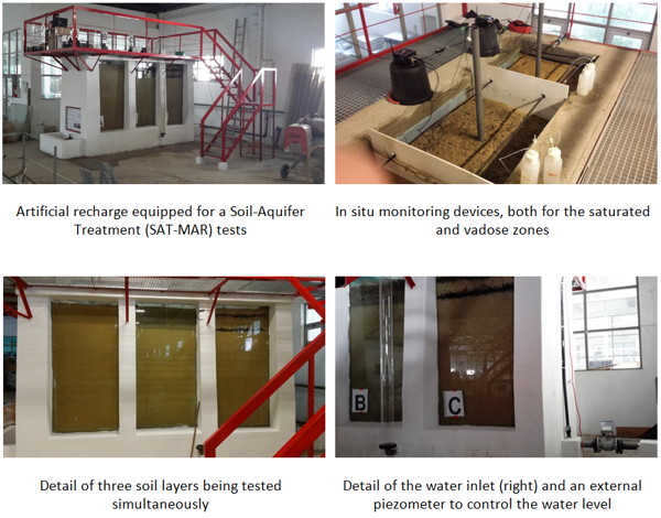 A complementary soil-column experiments apparatus is equipped to study the risk of pollutant leaching through soils and other materials using (1) batch experiments to assess the maximum concentrations of release in equilibrium conditions and (2) soil-columns facilities to quantify the movement of water and contaminants in dynamic conditions. Several other complementary tests can be performed to soil samples, like: humidity, density, porosity, and granulometry. 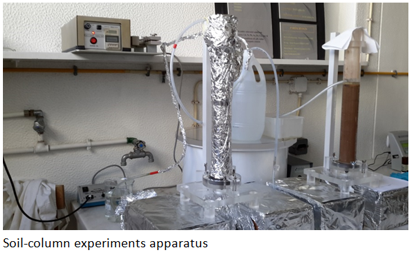 |