Summary:
The participation of the LNEC in the PGDL
is related to the hydraulic tests in a physical model of the vortex dropshafts
that make the connection and dissipate the energy between the flows at an upper
level and in the two deeper tunnels. The modelled vortex dropshaft stands for
the one that connects the drainage network of the area near Almirante Reis Street
and the tunnel between Monsanto and Santa Apolónia.
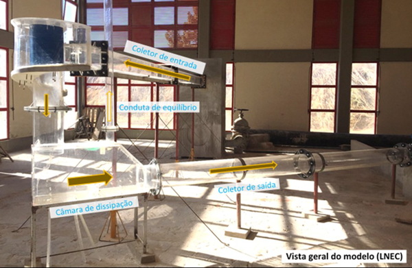
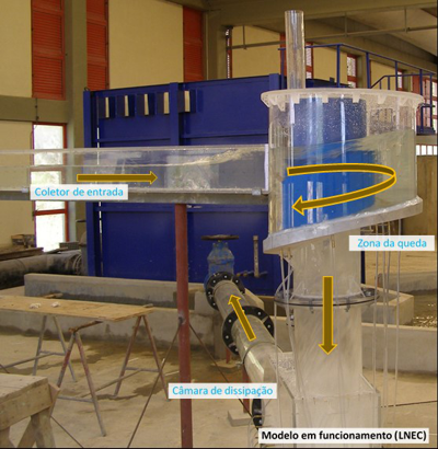
The model was constructed in the Hydraulic
Structures Pavilion of LNEC at the scale of 1: 11.6. The main components of the
vortex dropshaft were implemented, namely, the drainage pipe, the vertical drop
area including the vortex chamber, the dissipation chamber with the air vent and
the downstream pipe.
Whenever technically possible, the
construction of the model was carried out in transparent acrylic to allow the visualization
of the flow. Due to its size and geometry, the vortex chamber bottom was 3d printed.
This component and the vertical collector correspond to the connection between
the inlet pipe coming from Almirante Reis street, with an entrance elevation of
20 m, with the tunnel from Monsanto to Santa Apolónia at the elevation 6 m.
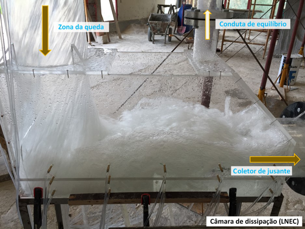
Through the simulation of a range of discharges,
the flow conditions in the several components of the physical model were
analyzed. Among these conditions, the free surface, the flow velocities and the
pressures in the bottom and the walls of the vortex structure and the
dissipation chamber were studied. In addition, the air flow rates in the
equilibrium air vent connecting the dissipation chamber to the exterior were
evaluated.
A better knowledge of the flow in this type of
structures were achieved in this study. Moreover, several recommendations have
been done for this project, namely, changes of specific geometrical dimensions and
the design of the structure in order to have good conditions for the flow of
discharges corresponding to the return period of up to 100 years.
Participant Institutions and Teams:CÂMARA MUNICIPAL DE LISBOA
LNEC:
HYADRAULICS AND ENVIRONMENT DEPARTMENT
João Nuno Fernandes
Postdoctoral Research
António Muralha
Junior Research Fellow
Ricardo Jónatas
Technical Fellow
STRUCTURES DEPARTMENT
Fernando Marques da Silva
Researcher
Officer
 Hydraulics and Environment Department